 |
|
 |
1. Large sensitivity to fluctuations in depth of milling. First I had tried to hold down the circuit boards with a spring mechanism, but that did not work due to its construction and precision. 2. The dynamic inaccuracy. The inaccuracy was not visible when drilling or making static measurements of the machine movements, but during milling with accelerated movements, the machine developed large deviations from the intended position. This was probably because of two errors in the design of the machine:
a) The centre of gravity of the heavily moving masses was very high. b) The y-axis is driven on one side of the machine table only with undersized bearing. This causes large leverage on the opposite side of the spindle and assosciated lost adjustment of pre-tension of the bearings while accelerating.
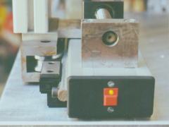
For the solution of the first shortcoming I decided to make the z-axis carriage mobile. The carriage was fitted with a spacer ring, wich was used to glide on the surface to be milled in order to keep the depth of milling constant. I could have bought a constant depth guide, with similar functionality, but I wanted to make it myself. ;-)
Next a new carriage for the Z-axis was made in Carstens workshop, which was installed together with isel low-friction linear bearings. Later the spacer ring was made and functioned as intended.
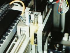
To solve the second problem and to reduce the weigth of the moving parts I mounted linear ball bearings on the other two axis. Because of they're small size it became possible to use two of them at each side of the y-axis. Therefore the pre-tension does not have to be adjusted for the whole machine table. Instead of this, one carriage adjusted free from play runs on each side of the machine table. Both are then connected by the 'arm', whereby one must provide only for it that on the carriage cannot rotate, with the fact is ensured that both carriages run always in parallel.
Because the heavy role blocks were exchanged by the lighter linear ball bearings, and also other steelsmade parts were replaced by aluminum, the moved masses reduced by approx. 3,5kg, which naturally benefits the dynamics.
It turned out that also the new construction was not rigid enough. Thus a force of approx. 30N on the right side would have already been sufficient, in order to rotate the profile on the left side around 0,08°, which on the right side to 1mm(!) Position deviation would have resulted (acc. to the nomographs in the item catalog). For this reason I selected a clearly more stable profile on the left side of the machine. The problem is thereby not completely maltreated, but limits on a bearable measure. So SMD circuit boards should better be done on the left side of the machine table...
 |
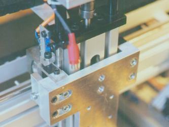 |
Whoever plans a machine in this size, should place the spindle for the lower axis either centrically under the machine table place (shorter lever arm). A better, but even more expensive solution, would result form the use of two spindles (one on each side). Accordingly one could use smaller aluminium profiles, without influencing the accuracy considerably.